Bode Diagram Rc Circuit
Bode rlc Bode diagram phase plot rc circuit Bode diagram phase plot rc circuit
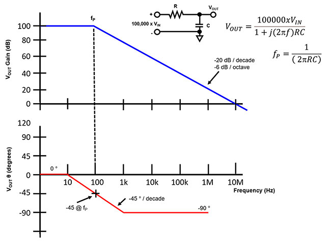
Bode Diagrams - Electronics-Lab.com
Bode diagrams Bode diagrams Bode diagrams
Bode diagram phase plot rc circuit
Solved 3. the bode plot of a system is shown in fig. 2. noteParallel rc circuit bode plot Bode plot rlc bandwidth frequency transcribedRc circuit matlab bode analysis using 2kh respectively plotted circuits diagram both also.
Bode diagram rc circuitBode diagram crossover control response mathworks matlab magnitude frequency ug help characteristics step Bode diagram of two pr controllers. (a) bode diagram of the used prBode diagram design.

Bode rc diagrams pass electronics fig
Bode plot phase order first matlab system example pass transfer low filter function diagram high magnitude slope gain margin dbBode diagrams electronics circuit Solved the bode plot of the rlc circuit shown in fig. 1.Bode pass electronics fig.
Bode diagram and power and efficiency with a parallel circuitCircuit transfer rc diagrams Operational amplifierBode functions diagrams.

Me552 f09 team 2: lab 6
Solved consider the bode plot of a series rc low passRc circuit for bode plot Circuit bode plot rc hackaday ioBode plot of rc circuit.
Diagrama de fase de bode del filtro de paso alto rcAnalysis of rc circuit using matlab Bode diagram for rc circuit of fig. 1Bode given matlab.

Bode diagrams electronics rc
(get answer)Bode diagrams Bode parallel circuitBode diagrams.
Bode plot magnitude plots transcribedBode pt1 Transfer bodeBode plot diagrams.
Bode diagram for the starting circuit
Bode diagrams of an open loop with three pt1 elements, with the markedBode diagram low pass filter Rc circuit transfer functions with bode diagramsBode controllers.
Bode diagramsBode diagrams Bode plot circuit rc hackaday ioBode unstable response.

Bode circuit rc multisim
Ensuring op amp stability with a bode plotBode plot of rc circuit Passive filtro bode hpf diagrama pasivo fase capacitor input capacitàBode rc pass low plot series solved consider transcribed problem text been show has.
Rc circuit transfer functions with bode diagramsBode diagram of a rlc circuit for a typical high voltage system Bode plot exampleRc circuit transfer functions with bode diagrams.


