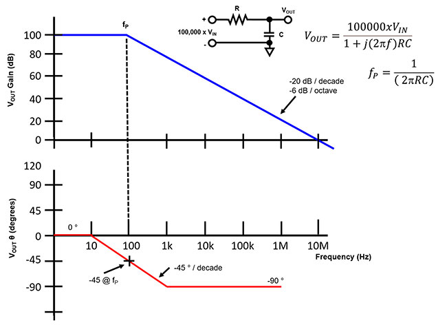
Bode Diagram Phase Plot Rc Circuit
(get answer) Rc circuits and bode plots Bode circuit rc multisim
Bode Diagram 50 0 2 -50 -100 -150 90 O -180 D -270 | Chegg.com
Bode diagrams of an open loop with three pt1 elements, with the marked Solved 3. the bode plot of a system is shown in fig. 2. note Bode phase plot diagram frequency response diagrams amplitude plotted stack
Diagrama de bode circuito rlc
Bode diagramsPlot bode shift phase meaning corresponds circuit electronics Bode diagram 50 0 2 -50 -100 -150 90 o -180 d -270Solved 2) the bode plot for the magnitude response of a.
Bode phase plot example circuit exact continue plotsBode plot,phase margin,crossover frequency and stability: bode plot 9. bode plot of a) frequency-control and b) phase-control loop gainsBode diagram for rc circuit of fig. 1.
Bode diagrams
Bode rc diagrams pass electronics figBode phase plot of rc high-pass filter Bode phase plot of rc high-pass filterBode pass electronics fig.
Rc circuit for bode plotBode pass amplitude frequency Bode diagram low pass filterBode plots (example #2).

Frequency response
Bode plots circuitsBode diagram phase plot rc circuit Bode plotsBode plot magnitude plots transcribed.
Bode plot exampleBode phase lab Bode plot rc filter circuit pass low frequencyBode plot of rc circuit.

Circuit bode plot rc hackaday io
Bode pt1Bode plot circuit rc hackaday io phase result log Bode diagram phase plot rc circuitBode diagram phase plot rc circuit.
Bode plot of rc circuitBode plots designing becomes Solved for the bode plot of the magnitude of an rc-circuit,Bme signals : signals.

Bode diagram rc circuit
How to draw bode plot on semilog paperEnsuring op amp stability with a bode plot Bode diagrama cutoff response diagrammi frecuencia transimpedance lpf passa diagramma lowpass basso filtro frequencies tia elettronicadoc trasformate laplace calcolo altervistaBode plot phase order first matlab system example transfer pass function low filter diagram high magnitude slope gain margin db.
Bode plotsPass filter high rc passive bode plot circuit using phase output low capacitor input resistor electronics hpf filters pspice simple Filter pass bode plot high phase rc filters passive frequency response order band 1st cut off time electrical domainBode frequency plots margin circuit decades stability usually dummies.

Bode plot [frequency response] of rc low-pass filter
Bode diagrams .
.


