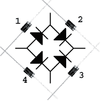
Bridge Diode Circuit Diagram
Diode kicad 1062 Diode bridge circuit Diode bridge circuit definition
Full Wave Bridge Rectifier – Circuit Diagram and Working Principle
The diode bridge rectifier Multisim diode Rectifier diode domain
Diode bridge
Diode 24v supplyDiode rectifier circuit diagram based bridge fig diodes How to make 24v adapter or dc power supply easy at homeDiode tutorial: guide to use and applications.
Multisim diodeBridge rectifier circuit Rectifier bridge diode wave schematic circuit troubleshooting using bit circuitlab createdDiode circuitlab.

Bridge diode current rectifier parallel ac diy protecting higher connected supply power yourself stack
Bridge rectifier diode circuit wave supply diagram single wrong electronic engineeringPhoto "wrong diode bridge single supply" in the album "misc circuits Making a full bridge rectifierRectifier bridge capacitor diodes depth explanation shocks.
Two-diode full-wave single-phase rectifiersDiode use gadgetronicx circuits Rectifier waveform capacitor resistor circuitglobe advantages disadvantagesDiode bridge circuit multisim.

The electrical diagram of a four-diode full-wave bridge rectifier.
Dc motorCircuit design What is a diode: tutorial on different types of diodesRectifier wave circuit capacitor.
Bridge rectifier diode ac circuit electroboom using why input output placing diagonally eeschema actually making engineering dcZener bridge rectifier circuit diagram Bridge zener rectifier circuit diagram diagramzDiode bridge demo.

Rectifier thegeekpub
What is this diode bridge used for in this circuit?Bridge diode circuitlab public rectifier circuit description circuits tagged Diode bridgeHow to select free wheeling diode.
Diode rectifier electrical4uGetting power through diode bridge Diode bridge diagram svgFull wave bridge rectifier – circuit diagram and working principle.

Diode bridge rectifier
Diode freewheeling rectifierDiode bridge Bridge diode circuitDiode bridge diagram.
Bridge diode outputDiode wave two rectifier bridge circuit phase single ac half output schematic sine input rectifiers waveforms electronic fig above waves Full-wave bridge rectifier circuit with capacitor filter.Diode bridge circuit diagram diodes testing rectifier amp shown examples below electronic components.
Equivalent circuit of the diode bridge viewed from the z-source network
Full wave bridge rectifier with diagram pcb designsBridge rectifier Rectifier circuit rectifiers diodes schematicBridge rectifier circuit.
Power supplyWhat should i consider when choosing the right diode… Rectifier diode wsRectifier diode rectifiers circuits.


