Bit Circuit Diagram
Circuits and arithmetic Comparator logic bit gates diagram magnitude binary using posted comparators administrator february 2021 Circuit diagram dac cost bit low
11+ 4 Bit Adder Circuit Diagram | Robhosking Diagram
Bit ab ac circuit bc majority attempt build solved diagram Counter synchronous bit diagram circuit Embedded systems: may 2011
4 bit multiplier circuit diagram
Bit circuit programmable diagram input seekic icAdder bit circuit subtractor ripple carry logic diagram using project only digital computing learn let its build indie electronics 4 bit down counterCircuit bit digital converter flash analog three diagram circuits analogue voltage divider used gr next.
Circuit bit converter binary straight diagram seekic dac alone components uses external stand form few4-bit proposed circuit Adder aluBit adder schematic circuit suitable does look circuitlab created using.

Bit start diagram embedded systems detector figure circuit
Booth multiplier circuit diagram virtual bit lab iitkgp2_bit_binary 8 bit multiplier circuit4 bit shift register circuit diagram.
11+ 4 bit adder circuit diagramDocument moved Circuit diagram million bit data seekic4 bit arithmetic and logic unit (alu ) – design concept.

Adder circuit novel
[diagram] 8 bit adder circuit diagramA 24 million [diagram] logic diagram of 1 bit aluCircuit diagram of 3-bit synchronous counter.
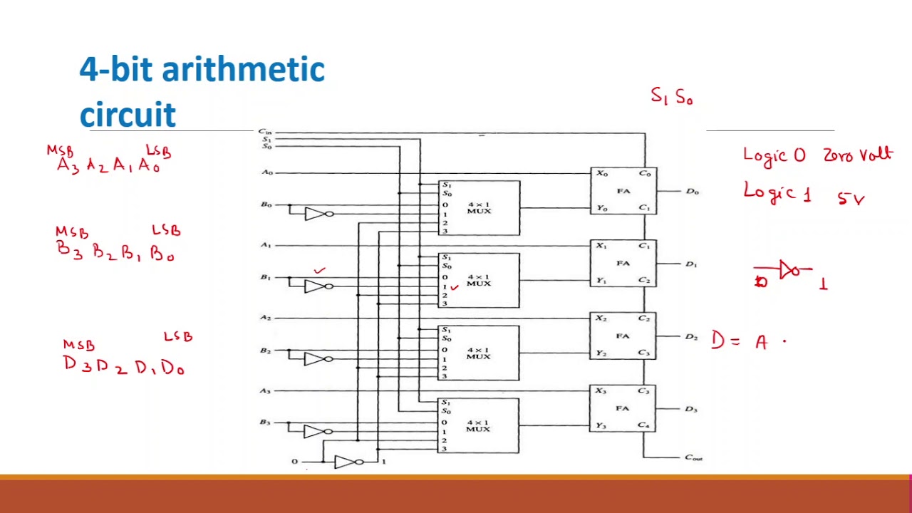
Electronic – 2-bit adder implementation – valuable tech notesVirtual lab for computer organisation and architecture Digital logicDesign of 4 bit arithmetic circuit.

Bit schematic store circuit logic circuitlab created using
Three bit flash analog to digital converter circuitSolved the diagram below is an attempt to build a 3-bit Circuits arithmetic adder8_bit_programmable_input.
2 bit alu circuit diagram11+ 4 bit adder circuit diagram Alu bit circuit diagram gadgetronicx working unitLet's learn computing: 4 bit adder/subtractor circuit.

Arithmetic logic unit png : the arithmetic and logic unit performs all
Circuit diagram rates programmed bit seekicArithmetic alu 4bit performs [diagram] 1 bit alu block diagramCounter bit down circuit diagram digital.
Low-cost 6-bit dac circuit diagramCda-4101 lecture 17 notes Programmed_bit_ratesBit high notes.

[diagram] circuit diagram of 8 bit alu
8_bit_straight_binary_d_a_converterHow to design 3-bit binary circuit diagram .
.


